Notice: Function _load_textdomain_just_in_time was called incorrectly. Translation loading for the quiri-hydromecanique-i18n domain was triggered too early. This is usually an indicator for some code in the plugin or theme running too early. Translations should be loaded at the init action or later. Please see Debugging in WordPress for more information. (This message was added in version 6.7.0.) in /var/www/vhosts/lafabrikk.dev/qri.lafabrikk.dev/wp-includes/functions.php on line 6114
Hydraulic schematic diagram: hydraulic system & cylinder diagram - Quiri close pdf print video more home burger search arrow

Hydraulic cylinders and components, hydraulic systems, gas springs & shell and tube heat exchangers : Quiri

Standard hydraulic diagrams

Print this guide

Equipment for one or several single acting cylinders

Motor in function only during operation

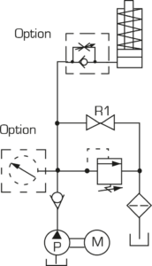
DM 2/2 (manual operated valve)

Standard hydraulic diagrams : Electro hydraulic pumps - Quiri

Cylinder advance: Start motor. Close R1
Cylinder hold: Stop motor
Cylinder retract: Open R1

Options :

• Braking valve
• Pressure gauge ø 63 ( ø 100 on request)

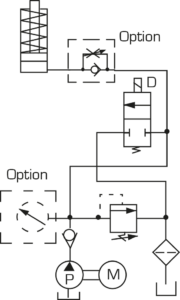
DE 2/2 (solenoid operated valve)

Standard hydraulic diagrams : Electro hydraulic pumps - Quiri - 2

Cylinder advance: Start motor
Cylinder hold: Stop motor
Cylinder retract: Activate D

Options :

• Braking valve
• Pressure gauge ø 63 (ø 100 on request)

Equipment for one or several single acting cylinders

Motor always in function

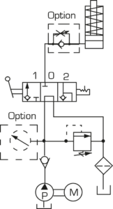
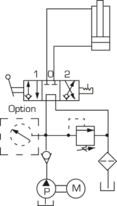
DM 3/3 (manual operated valve)

Standard hydraulic diagrams : Electro hydraulic pumps - Quiri - 3

Cylinder advance: Valve in position 1
Cylinder hold: Valve in position 0
Cylinder retract: Valve in position 2

Options :

• Braking valve
• Pressure gauge ø 63 ( ø 100 on request)

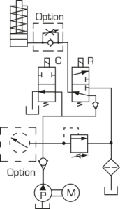
DE 3/3 (solenoid operated valve)

Standard hydraulic diagrams : Electro hydraulic pumps - Quiri - 4

Cylinder advance: Activate C
Cylinder hold: C and R off
Cylinder retract: Activate R

Options :

• Braking valve
• Pressure gauge ø 63 ( ø 100 on request)

Equipment for one or several double acting cylinders

Motor always in function

DM 4/3 (manual operated valve)

Standard hydraulic diagrams : Electro hydraulic pumps - Quiri - 5

Cylinder advance: Valve in position 1
Cylinder hold: Valve in position 0
Cylinder retract: Valve in position 2

Option :

• Pressure gauge ø 63 ( ø 100 on request)

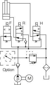
DE 4/3 (solenoid operated valve)

Standard hydraulic diagrams : Electro hydraulic pumps - Quiri - 6

Cylinder advance: Activate F
Cylinder hold: F, R and H off
Cylinder retract: Activate F, R and H

Option :

• Pressure gauge ø 63 ( ø 100 on request)

Equipment for several cylinders simultaneaously or separately

Motor always in function

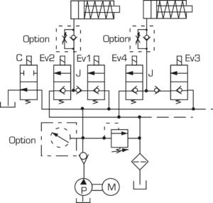
Single acting cylinders

Standard hydraulic diagrams : Electro hydraulic pumps - Quiri - 7

Cylinder advance: Activate C, Ev1 or Ev3
Cylinder hold: C and J off
Cylinder retract: Activate Ev2 or Ev4

Options :

• Braking valve
• Pressure gauge ø 63 ( ø 100 on request)

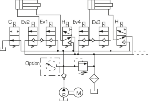
Double acting cylinders

Standard hydraulic diagrams : Electro hydraulic pumps - Quiri - 8

Cylinder advance: Activate C, Ev2 or Ev4
Cylinder hold: C, J and H off
Cylinder retract: Activate C, H and Ev2 or Ev5

Option :

• Pressure gauge ø 63 ( ø 100 on request)

Print this guide

Si vous n’avez pas encore de compte, veuillez nous adresser
votre demande via le formulaire de contact.

This site is registered on wpml.org as a development site. Switch to a production site key to remove this banner.