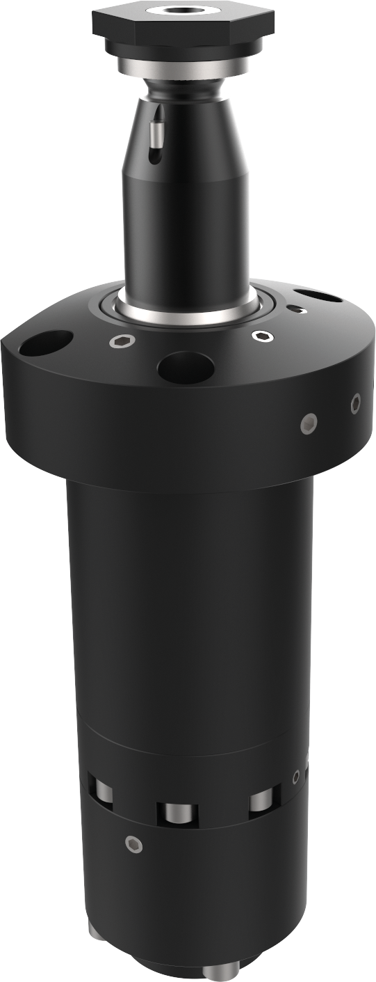
Supply through counter-bores under the flange ring

Swing clamps with position detection
Other products
Access Swing clamps with position detection 's products
Access selection
Back to Hydraulic Clamping Systems
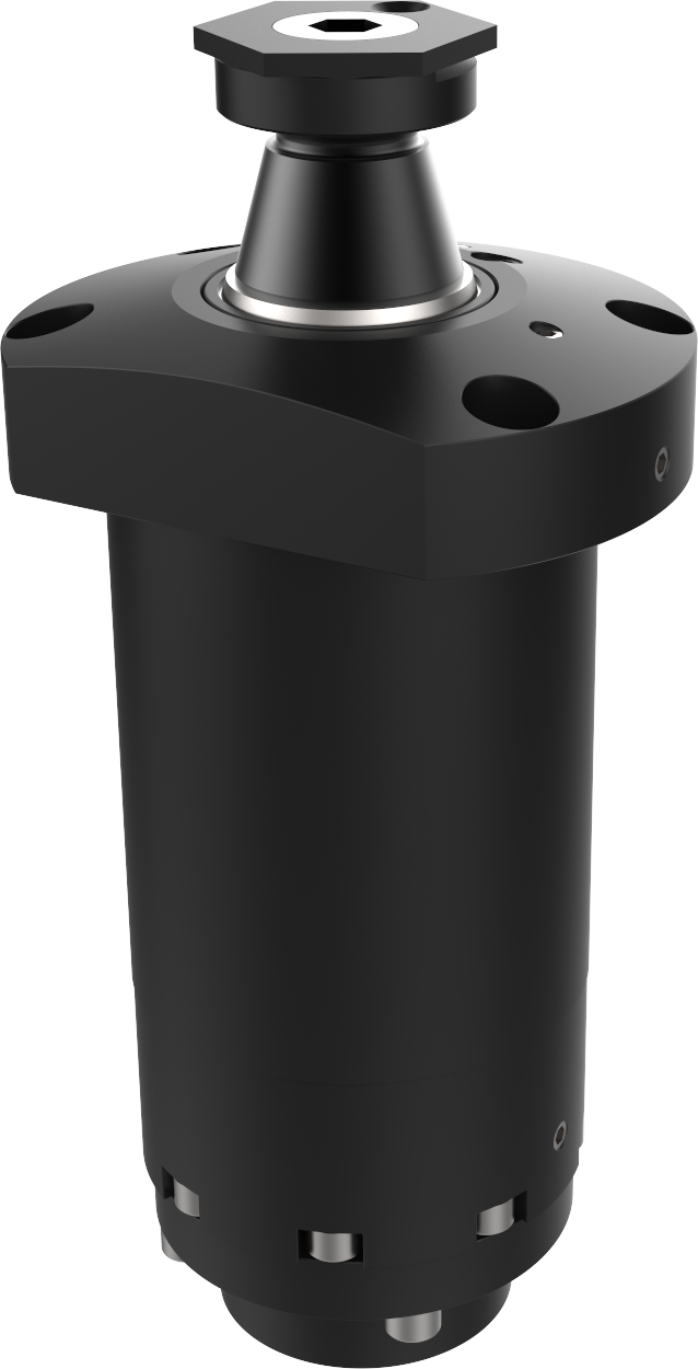
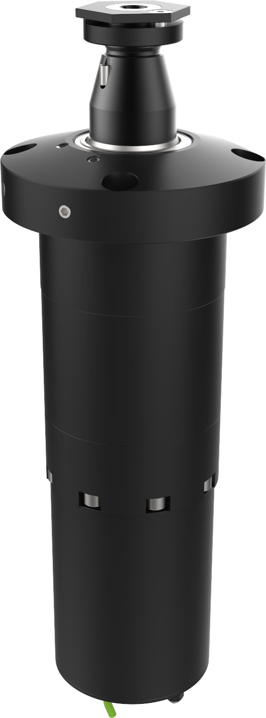
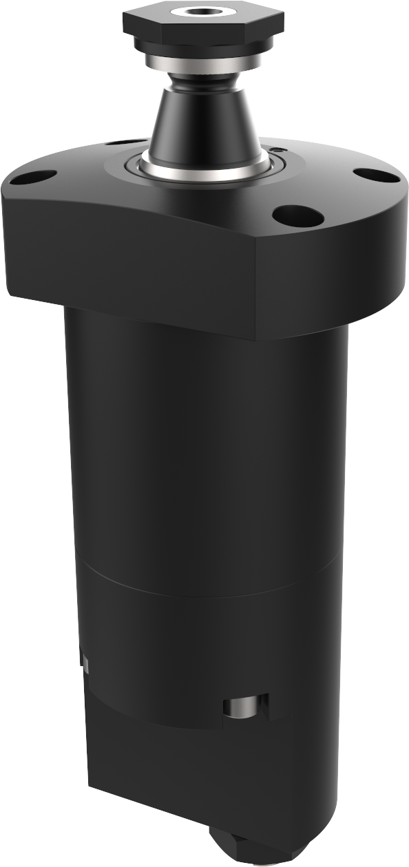
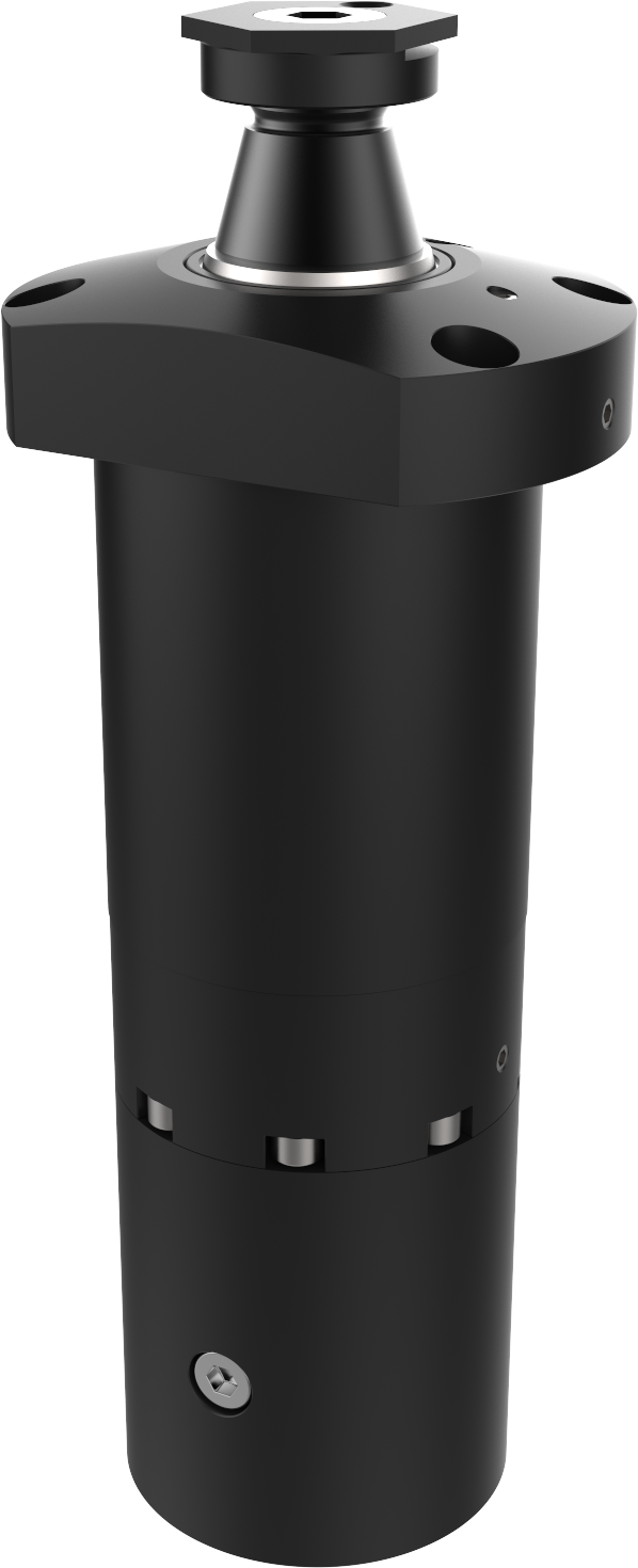
Swing clamp with planar rotation – 160 bar – Pneumatic sensing of released and clamped position PL**XB12
Double-acting - planar rotation - pneumatic sensing of clamped and released position Force at 160 bar: 10 kN
• detection of clamped and released position by adjustable
• leak-free valves
• left or right planar rotation, 90°±2°
• bleeders on clamping and release side
• rod indexing
• max. pressure: 160 bar
• clamping arm: see accessories section
• 60°, 45° or 0° rotation on request
The clamps are supplied with O-rings, lock nut and lock washer (dimensions: see Lock washer for clamp type P11, P21 and Nut for clamp type P31 and P41)
O-rings: 7.65 x 1.78 90 NBR

Definition of forces depending on clamping arm: consult the guide
Important recommendations: consult the guide
| F max
at 160 bar |
Rod
ød |
Travel | Max flow rate
A |
Swept volume
A B |
Direction
of rotation |
Type | Reference | |||||||||||||||
| a
|
c
|
øD
|
e
|
f
span-ner |
h
|
øk1
øk2
|
L
|
L1
|
L2
|
L3
|
m
|
p1
|
p2
|
p3
|
||||||||
| kN | mm | mm | l/min | cm3 | mm | mm | mm | mm | mm | mm | mm | mm | mm | mm | mm | mm | mm | mm | ||||
| 10 | 36 | 12 | 2 | 41 | right | PL 31 DX B12 | 192 142/050 | 18 | 20 | 80 | M24 x 1.5 | 10 | 41 | 110 | 301.5 | 248.5 | 220.5 | 43 | 29 | 8.5 | 14 | 11 |
| 53 | left | PL 31 GX B12 | 192 142/150 | 95 | ||||||||||||||||||