Supply through counter-bores under the flange ring

Swing clamps with position detection
Other products
Access Swing clamps with position detection 's products
Access selection
Back to Hydraulic Clamping Systems
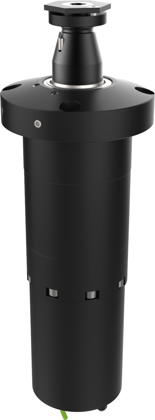
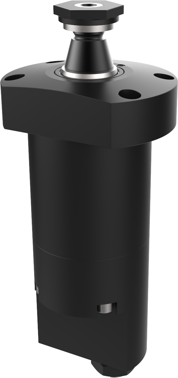
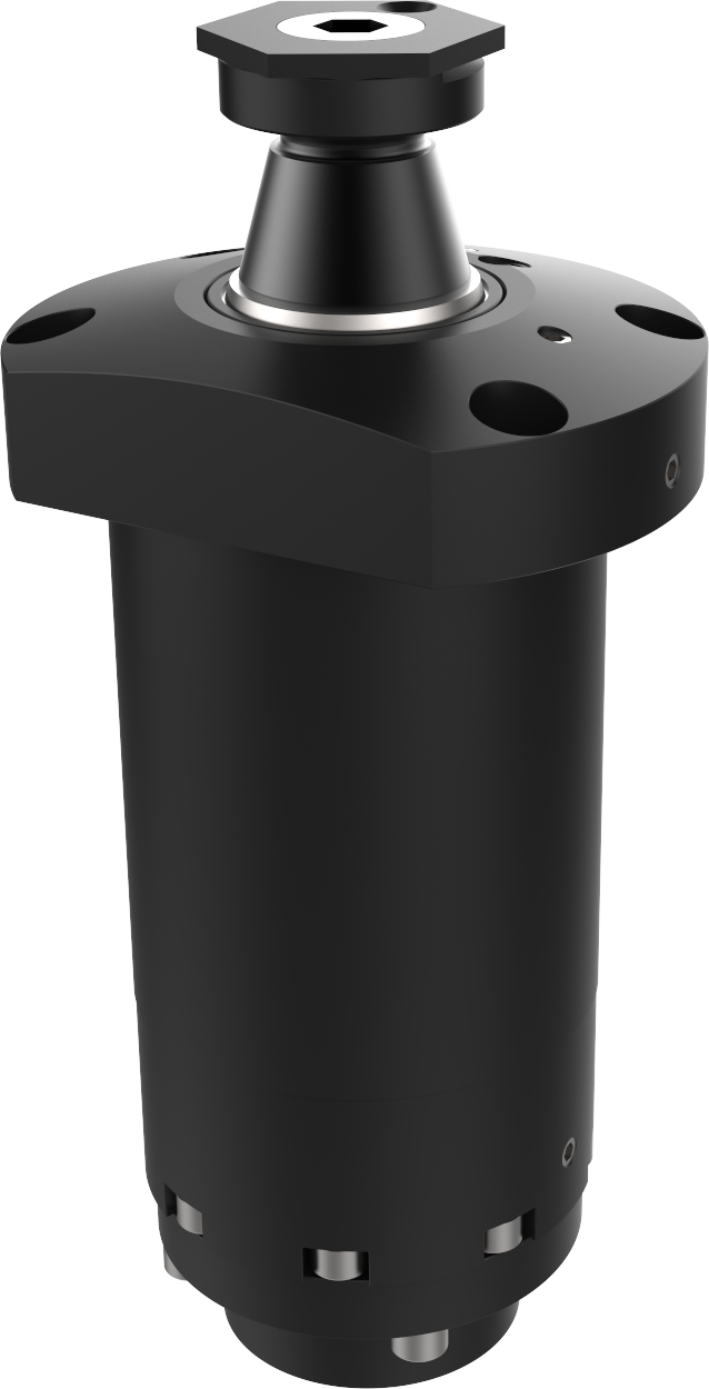
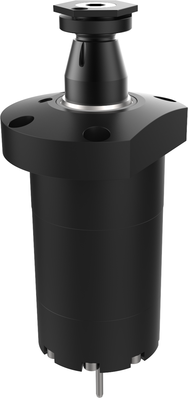
Swing cable with helical rotation – 250 bar – Pneumatic sensing of released position HLF**XB1
Double-acting - with helical rotation - pneumatic released position sensing
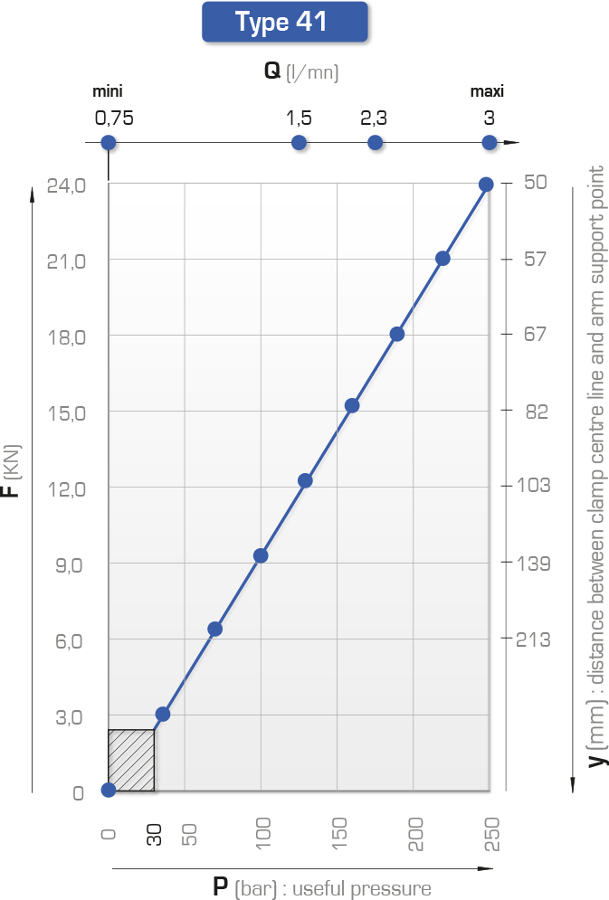
Force at 250 bar: 11.8 to 36.5 kN
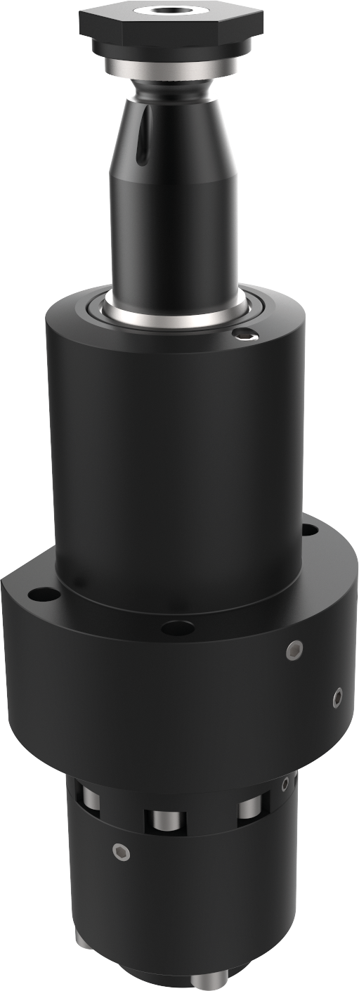
• detection by leak-free valves, released position
• right or left planar rotation, 90° ±2°
• bleeder near clamping and release
• rod indexing
• maximum service pressure: 250 bar
• clamping arm: see accessories section
• 60°, 45° or 0° rotation on request

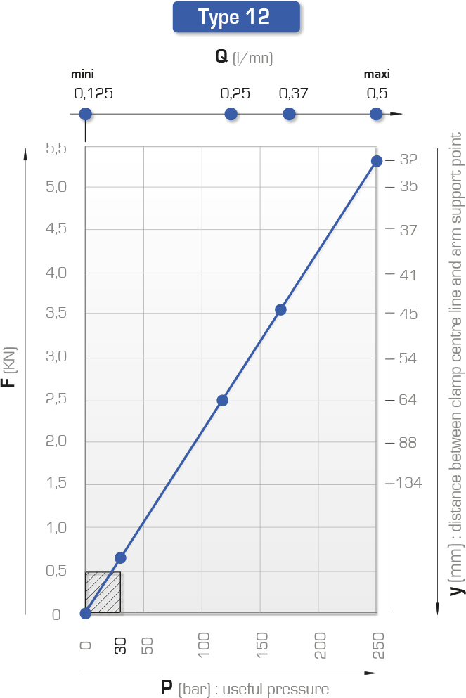
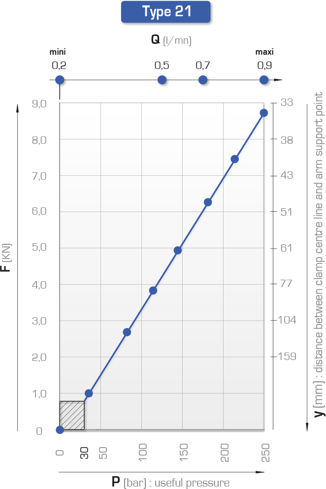
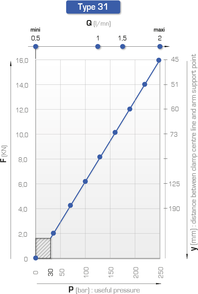
Definition of forces depending on clamping arm: see below
Important recommendations: consult the guide
| F max
at 250 bar |
Rod
ød |
Travel
of torque |
Travel
total
|
Max flow rate
A |
Swept volume
A B |
Direction
of rotation |
Type | Reference | ||||||||||||||
| a
|
b
|
øD
|
ød
|
e
|
f
span-ner |
h
|
øk1
øk2
|
L1
|
L2
|
L3
|
L4
|
øm
|
øp1
|
|||||||||
| kN | mm | mm | mm | l/min | cm3 | mm | mm | mm | mm | mm | mm | mm | mm | mm | mm | mm | mm | mm | ||||
| 11.8 | 12 | 12 | 24 | 0.7 | 11.33 | right | HLF 21 DX B1 | 191 241/050 | 16 | 14 | 52 | 25 | M16 x 1.5 | 6 | 28 | 76 | 123 | 64 | 34 | 90 | 8.8 | 6.5 |
| 18.87 | left | HLF 21 GX B1 | 191 241/150 | 63 | ||||||||||||||||||
| 23.6 | 15 | 14 | 29 | 1.6 | 27.44 | right | HLF 31 DX B1 | 192 160/050 | 18 | 20 | 72 | 36 | M24 x 1.5 | 10 | 38 | 110 | 152.5 | 75 | 36 | 111.5 | 11 | 10.5 |
| 49.60 | left | HLF 31 GX B1 | 192 160/150 | 90 | ||||||||||||||||||
| 36.5 | 15 | 17 | 32 | 2.8 | 46.15 | right | HLF 41 DX B1 | 192 231/050 | 20 | 22 | 88 | 42 | M30 x 1.5 | 10 | 45 | 128 | 164.5 | 82 | 36 | 116.5 | 11 | 10.5 |
| 80.45 | left | HLF 41 GX B1 | 192 231/150 | 108 | ||||||||||||||||||
Product charts