Supply through counter-bores under the flange ring or through gas fittings

Link clamp cylinders
Other products
How to choose a Link clamp cylinders Guide ?
Access Link clamp cylinders 's products
Access selection
Back to Hydraulic Clamping Systems
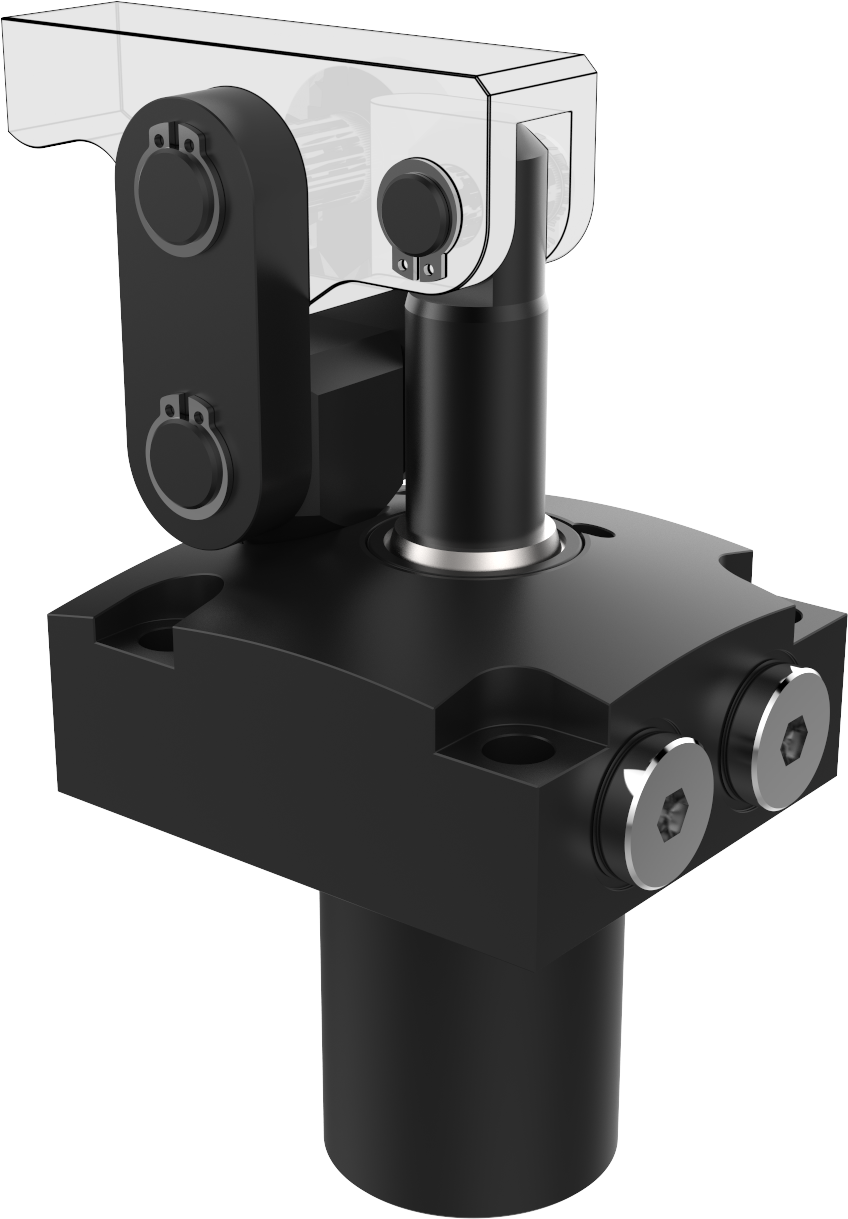
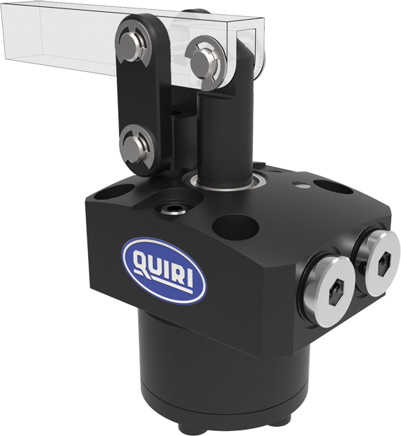
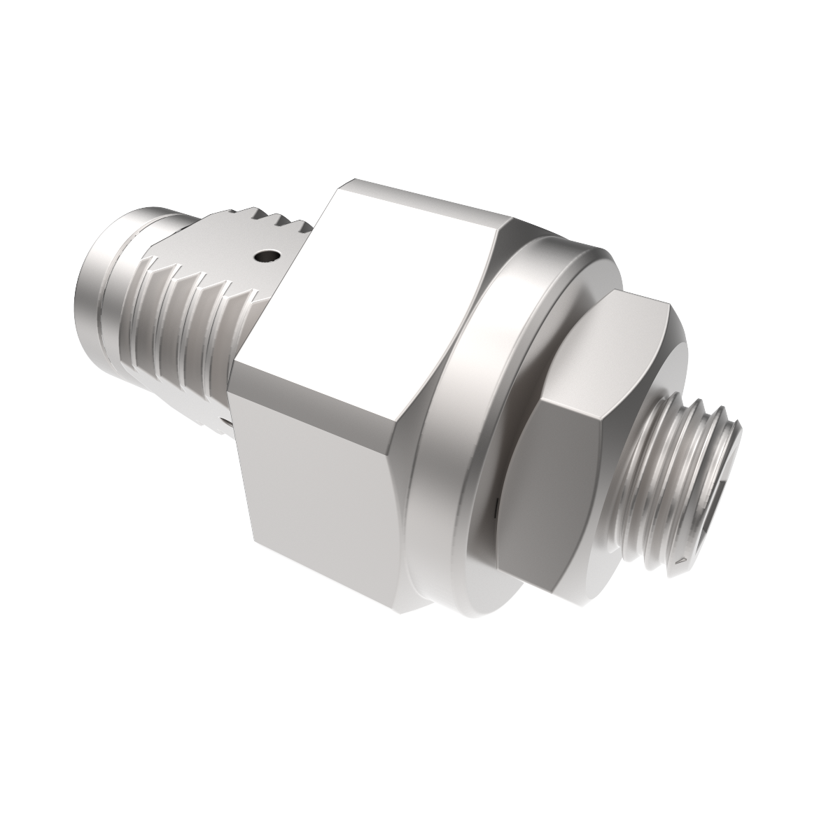
Link clamp cylinders 70 bar BL7
Double-acting - linear clamp cylinder
Maximum force at 70 bar: 2.6 to 13.5 kN
• fastening and supply flange at the top of the clamp
• supplied with supply O-rings
• rod and connecting rods supplied with pins and circlips but with no clamping arm
• versatility of cylinders, 3 lever direction are possible with only one cylinder reference
• steel body with anti-corrosion treatment
• steel rod treated to prevent seizing and corrosion
• clamping arm: see clamping arms for BL7
• metal scraper
Clamping force (Fb) depending on the arm length (h) and pressure (P)
Fb = ( S x P x l x 0.9 )/h
S = piston surface in cm²
l = clamp/connecting rod centre distance in mm
P = service pressure in Bar
h = centre distance between connecting rod and clamping point in mm

Part number without flange: ******/000
Part number with standard flange: ******/100
Optional metal scraper: ******/*5*
Part numbers of packs of spare seals for BL7 clamp: 14x xxx/900
Example: the part number for a BL7-55 clamp is: 141C54//900
| Clamping
force at (g+h) in mm |
P Maxi | Section
A B |
Swept volume
A B |
ø
Piston Rod |
Working stroke
Total stroke |
Max flow rate | Type | Reference | |||||||||||||||||||||||||||||||||
| a1 | a2 | a3 | øa4 | b | øc1 | øc2 | d1 | d2 | g | h | i | k | øl | øm | øm1 | n | n1 | p | q | r | r1 | r2 | s | t | u1 | u2 | øv | øw | øw1 | x | y | z screw HC |
|||||||||
| kN | bar | cm2 | cm3 | mm | mm | l/mn | mm | mm | mm | mm | mm | mm | mm | mm | mm | mm | mm | mm | mm | mm | mm | mm | mm | mm | mm | mm | mm | mm | mm | mm | mm | mm | mm | mm | mm | mm | |||||
| 2.6 | 70 | 4.9 | 8.6 | 25 | 17.5 | 1 | BL7-40 | 141C52/100 | 54 | 45 | 22.5 | 72 | 30 | 40 | 40 | 58.5 | 100.7 | 16 | 53.5 | 69.5 | 24.5 | 9.1 | 5.5 | M5 | 34 | 17 | 15 | 11 | 26 | 18 | 18 | G1/8″ | 50 | 30.5 | 220 | 9 | M4 | 4 | 14 | 44.5 | M4 |
| 3.8 | 6.6 | 12 | 20.5 | ||||||||||||||||||||||||||||||||||||||
| 3.9 | 70 | 7.1 | 14.5 | 30 | 20.5 | 2 | BL7-48 | 141C53/100 | 61 | 51 | 25.5 | 81 | 32 | 48 | 48 | 65.5 | 114.5 | 18.5 | 61 | 79.5 | 28 | 9.1 | 5.5 | M5 | 40 | 20 | 16 | 12 | 30 | 22 | 22 | G1/8″ | 57 | 34.5 | 26 | 9 | M4 | 4 | 14 | 52 | M4 |
| 5.5 | 11.3 | 14 | 23.5 | ||||||||||||||||||||||||||||||||||||||
| 4.9 | 70 | 9.6 | 22.1 | 35 | 23 | 2.4 | BL7-55 | 141C54/100 | 69 | 60 | 30 | 88 | 37 | 54 | 55 | 73.5 | 120.3 | 21 | 63 | 84 | 28 | 9.1 | 6.8 | M6 | 47 | 23.5 | 13.5 | 12 | 33.5 | 24 | 24 | G1/8″ | 59.5 | 35.5 | 30 | 11 | M4 | 4 | 20 | 53.5 | M4 |
| 8.1 | 18.6 | 14 | 26 | ||||||||||||||||||||||||||||||||||||||
| 8.1 | 70 | 12.6 | 33.4 | 40 | 26.6 | 5 | BL7-65 | 141C55/100 | 81 | 70 | 35 | 106 | 43.5 | 65 | 65 | 84 | 137.3 | 24.5 | 72.5 | 97 | 30 | 11.1 | 6.8 | M6 | 55 | 27.5 | 16 | 13 | 39.5 | 30 | 30 | G1/4″ | 67 | 39 | 35.5 | 11 | M5 | 5 | 25 | 59 | M5 |
| 10.6 | 28.1 | 16 | 28 | ||||||||||||||||||||||||||||||||||||||
| 13.48 | 70 | 24.6 | 78.7 | 56 | 32 | 9 | BL7-75 | 142B35/100 | 94.5 | 85 | 42.5 | 118 | 47 | 75 | 75 | 104 | 151.1 | 30 | 70 | 100 | 36 | 11.1 | 9 | M8 | 63 | 31.5 | 17.5 | 16 | 45 | 32 | 32 | G1/4″ | 82 | 48 | 43.5 | 14 | M6 | 6 | 32 | 72 | M6 |
| 20.8 | 66.5 | 22 | 34 | ||||||||||||||||||||||||||||||||||||||
Product accessories
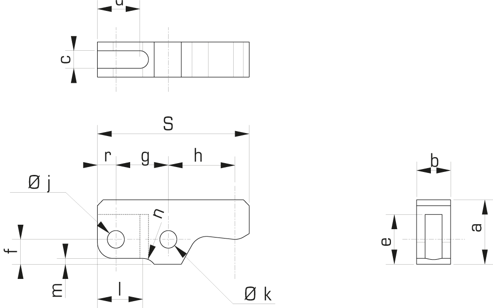
Clamping arm for BL7 LS7 / LL7
For link clamp cylinders BL7
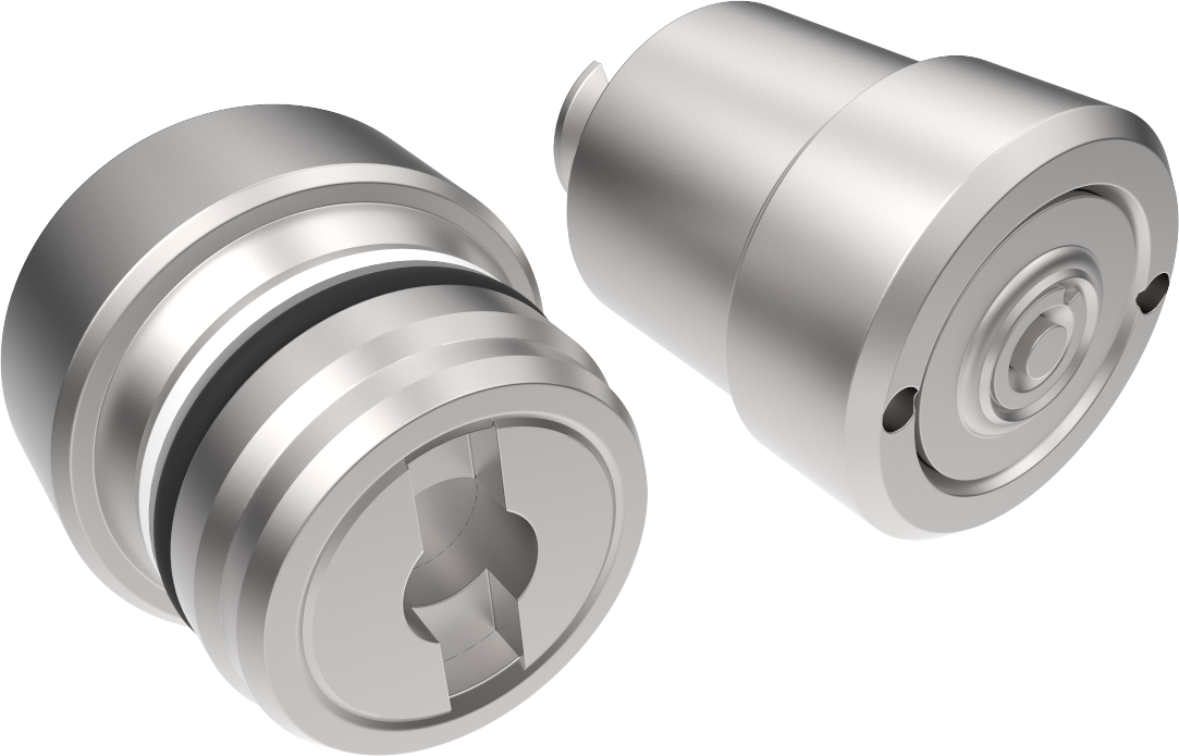
Self-Coupler M20x1.5
Screw-in coupling mechanism.
Operating pressure from 5 to 350 bar.
Flow 12l/min at 70 bar. Max flow 20l/min.
Flow limiter – SCV
Compact flow limiter/brake for installation on a cylinder.
Operating pressure between 10 and 110 bars.